
Should you model hydraulic components and systems with a lumped-parameter approach (0D) or with computational fluid dynamics (CFD)? It isn't an ideological choice, but a technical one — and the answer is often "both."
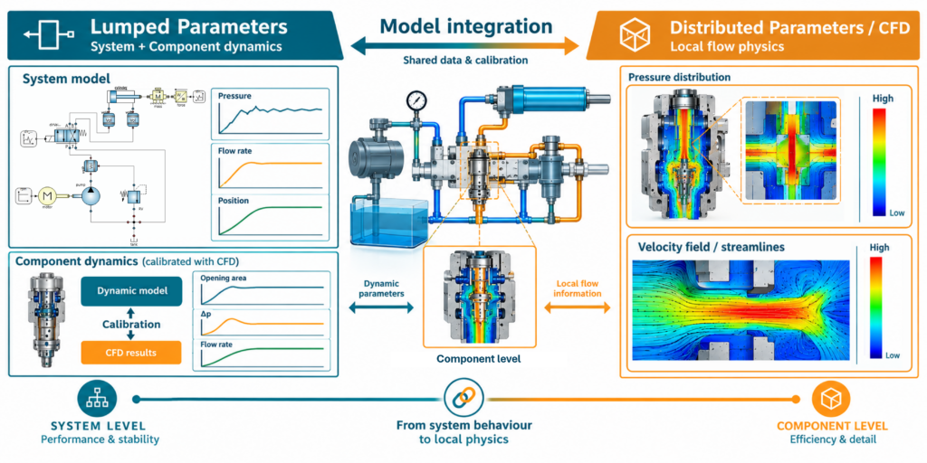
Computer simulation is now an indispensable tool for designing and optimizing hydraulic components and systems — pumps, valves, actuators, complete circuits. Two families of approaches exist, both well established, both still evolving.
🧩 Two Ways to Discretize the Same Fluid
The 0D (lumped-parameter) model divides the fluid volume into a few homogeneous control volumes — for example, one chamber for each pair of teeth in a gear pump, plus the inlet and delivery ducts. The CFD model instead discretizes the same domain into a multitude of elementary cells, typically up to a few million, solving the flow field point by point.
Neither approach is inherently tied to a problem scale: both apply as much to a single component as to a complete system, and the choice depends on the phenomenon to be captured, not on the size of the object being studied.
⚙️ Lumped-Parameter Simulation: Strengths and Limits
Computation times are orders of magnitude lower than CFD — minutes rather than hours — which makes 0D suited both to optimization across many configurations and, simply, to getting quick results or at least reliable trends. It’s also used frequently on a single component: mentally breaking down the fluid domain into homogeneous control volumes takes experience, but once acquired it lets you move from concept to a first numerical result far faster than with CFD. On geometrically more complex components, the 0D model naturally has to become more articulated, with more control volumes and more resistive elements — the speed advantage remains, but shrinks.
The main limits concern the physics the model can represent. Kinematics must be simplified, so complex motions or real micro-movements of components fall outside its reach. On top of this comes the need to experimentally calibrate certain parameters (such as flow coefficients and flow forces) — calibration that doesn’t always remain valid as geometry changes — plus reduced flexibility in customizing the model for non-standard features (particular fluids, unusual geometries).
🌀 CFD: Strengths and Limits
CFD’s strength is geometric fidelity: you can start directly from CAD geometry, with no need to break it down by hand into control volumes, and evaluate flow through complex shapes without simplifying assumptions about the flow regime — even when no known analytical formulation exists, as with particular gear-tooth profiles or specially machined port plates. This makes it the natural tool for reproducing inherently three-dimensional phenomena, such as incomplete chamber filling at high speed.
The cost of this fidelity is computation time, which grows further when the mesh has to be refined over geometrically very small areas — the typical case of internal leakage flows, where the flow rates involved are minimal but their accurate estimation requires fine discretization, at a computational cost that is often disproportionate to the benefit. Complexity rises further with dynamic, moving-mesh CFD, needed when the position of an element (a poppet, a spool) is itself the result of a fluid-force balance: the mesh has to deform and regenerate during the simulation. Even an accurate CFD model, moreover, still benefits from calibration against experimental data, though only as a refinement.
🎯 0D Only, CFD Only, or Both Together?
The choice depends on the phenomenon under study, the component or system involved, and the software actually available:
- 0D only: when a quick result or a reliable trend is what’s needed — on a component still being sized just as much as on a complete system — or when many design iterations are required in a short time
- CFD only: when the phenomenon is inherently three-dimensional — local flow forces on a poppet, non-uniform fluid distribution in a chamber — and no reliable analytical shortcut exists
- Both, in synergy: the most frequent case in industrial practice. The 0D model quickly explores the configuration space and identifies critical points; CFD, applied selectively to those points, validates the local detail and feeds data back to recalibrate the 0D model itself
In published validation cases, the difference between the two approaches on the mean values of the calculated quantities can drop below 1% — but only when the phenomenon under study lends itself to both representations. In other cases, the gap between the two predictions becomes significant, and that’s where the synergy between the two models makes the difference.
📌 In Summary
There is no absolute best approach, nor a rule that ties 0D to systems and CFD to components. The choice — and any combination of the two — depends on the physical phenomenon to be captured, the geometry involved, and the time available to reach a reliable answer.
🔗 How We Approach It at SmartFluidPower
Our approach is built on SFPLibDyn, a proprietary lumped-parameter simulation library for OpenModelica, designed for both individual components and complete hydraulic systems. It doesn’t replace CFD: it complements it, reducing the number of cases where a 3D analysis is needed and concentrating computational effort where it’s genuinely required.
See whether SmartFluidPower is the right fit for your company
With our intuitive, scalable simulation software, you can virtually model hydraulic components, with no limit on configurations to test.
From day one, you’ll be supported by our specialized technical team, providing the know‑how your engineering department needs to tackle future challenges.
With this type of simulation, you can visualize your component or system behaviour, and how it interacts with all other elements.
If you’re struggling with a critical component, this approach may be exactly what you need.
Training for companies (modular tailored to user level):
- Hydraulics
- Modeling and simulation
- Interface creation
