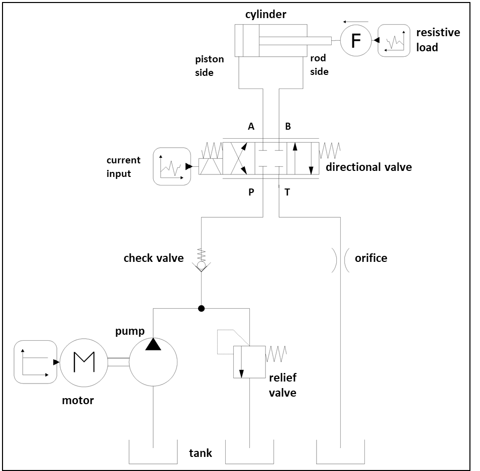
Diagram of a hydraulic circuit which, by commanding a distributor, extends a cylinder with a resistant load. In particular, the circuit parameters are:
- fixed displacement pump with pressure relief valve in parallel
- check valve in series and in port P of the distributor
- 4/3 closed center distributor
- single-acting cylinder with piston side in port A and rod side in port B of the distributor
- oririce in port T of the distributor
The circuit is modeled in OpenModelica with the SmartFluidPower logic virtual library that allows you to check its functionality and generate a diagram according to ISO 1219.
The model is parameterized with the values of the hydraulic circuit components and the operating conditions of the test. The parameters used are shown below:
- pump with constant flow rate of 15 l/min (1500 rpm of the motor and 10 cc of the pump)
- pressure relief valve (cracking pressure 100 bar)
- check valve (cracking pressure 2 bar)
- distributor 4/3 with:
- pressure drops P-> A and P-> B: 3 bar @ 20 l/min
- pressure drops A-> B and A-> T: 1 bar @ 20 l/min
- complete switching with 1 A signal
- cylinder with 25 mm piston diameter and 12 mm rod diameter
- constant load of 3 kN
- orifice with pressure drop of 2 bar @ 30 l/min
- signal to the distributor:
- 0, from 0s to 1s
- 1, from 1s to 1.2s
- 1, from 1.2s to 2s
The results of the hydraulic circuit simulation are shown in terms of pressures, flow rates and cylinder stroke as a function of the 2 s operating cycle time.
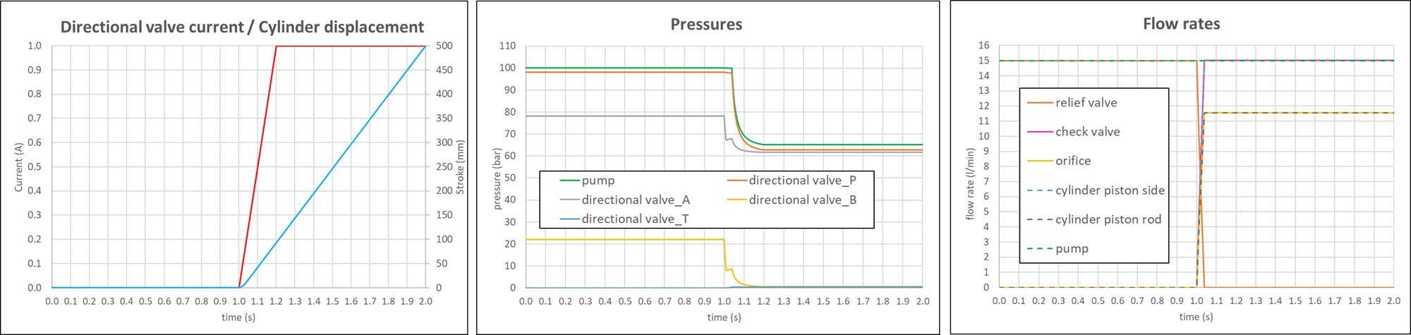
This type of simulation mainly allows to verify the functionality of the system, for example flow rates and pressures in different points of the circuit during the work cycle, but also to estimate its performances such as the powers and efficiencies involved.