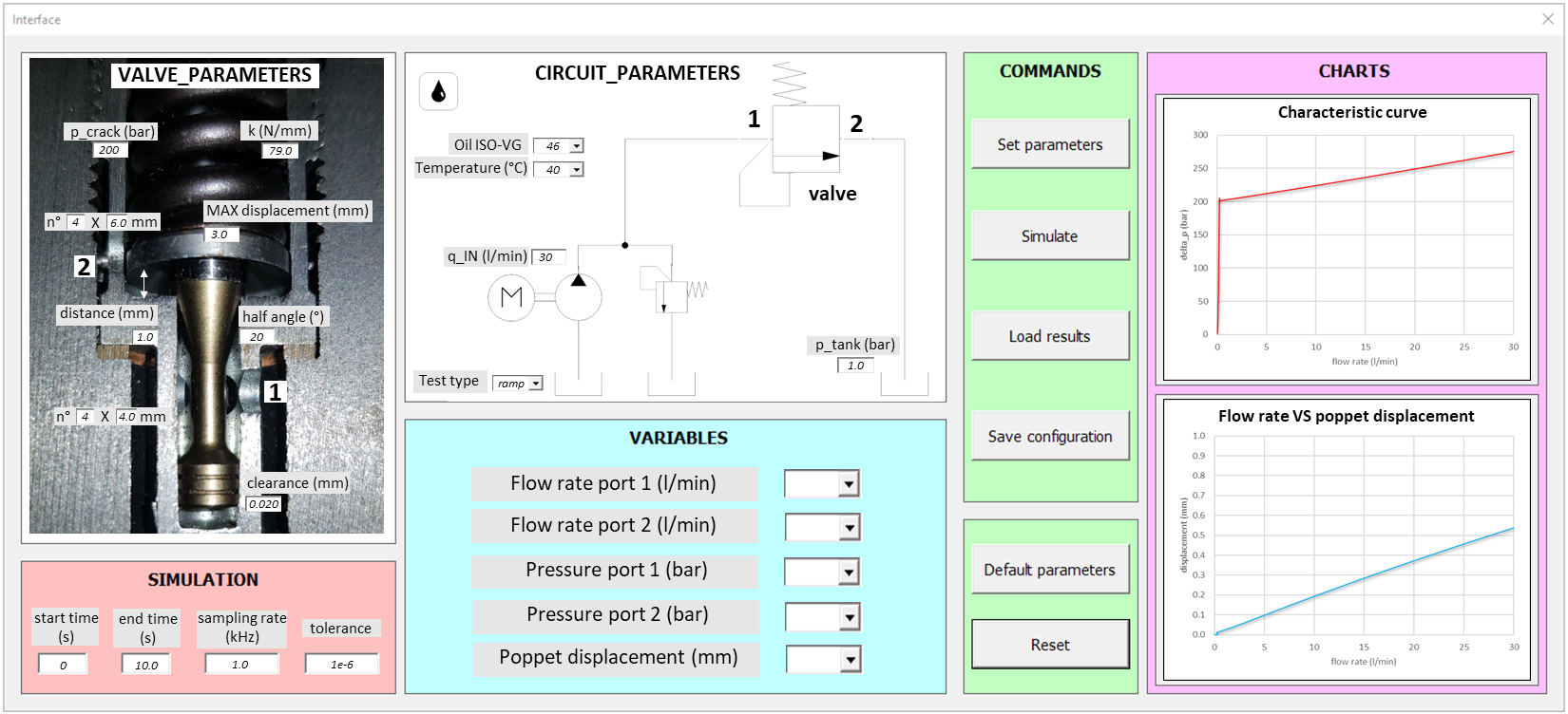
The user interfaces have simplified the simulations of a virtual prototype, showing the operations to be done in an intuitive way and allowing a quick modification of the parameters to be set. They are fully customizable in the number of parameters ‘open’ to modification, in functionality and graphics. Generally the operations to launch a simulation are included in the following sections:
- ‘PARAMETERS’ in which the parameters of the valve and the test circuit, indicated in correspondence with the diagrams / drawings of the modeled system, are set
- ‘SIMULATION’ with the simulation parameters
- ‘VARIABLES’ with the choice of simulation results to be monitored
- ‘COMMANDS’ with various buttons to check the entered parameters, launch simulations, import and save results, reset the interface
- ‘CHARTS’ area with the main graphs to be displayed
User interface of the virtual prototype of the pressure relief valve modeled here.