Direct cartridge pressure relief valve with variable setting and guided conical poppet. Maximum flow 30 l/min and maximum pressure in port 1 of 420 bar. The valve is tested with two types of input in port 1 (port 2 to tank), with 4 different cracking pressures (50, 100, 200 and 300 bar) and, therefore, different springs, and with ISO-VG 46 oil at 40 ° C:
- Flow rate ramp from 0 to 30 l min in 10 s to simulate the pressure drop
- Flow rate step from 0 to 30 l/min (almost ideal in 0.01 s) to check the functionality of the vibration damping system
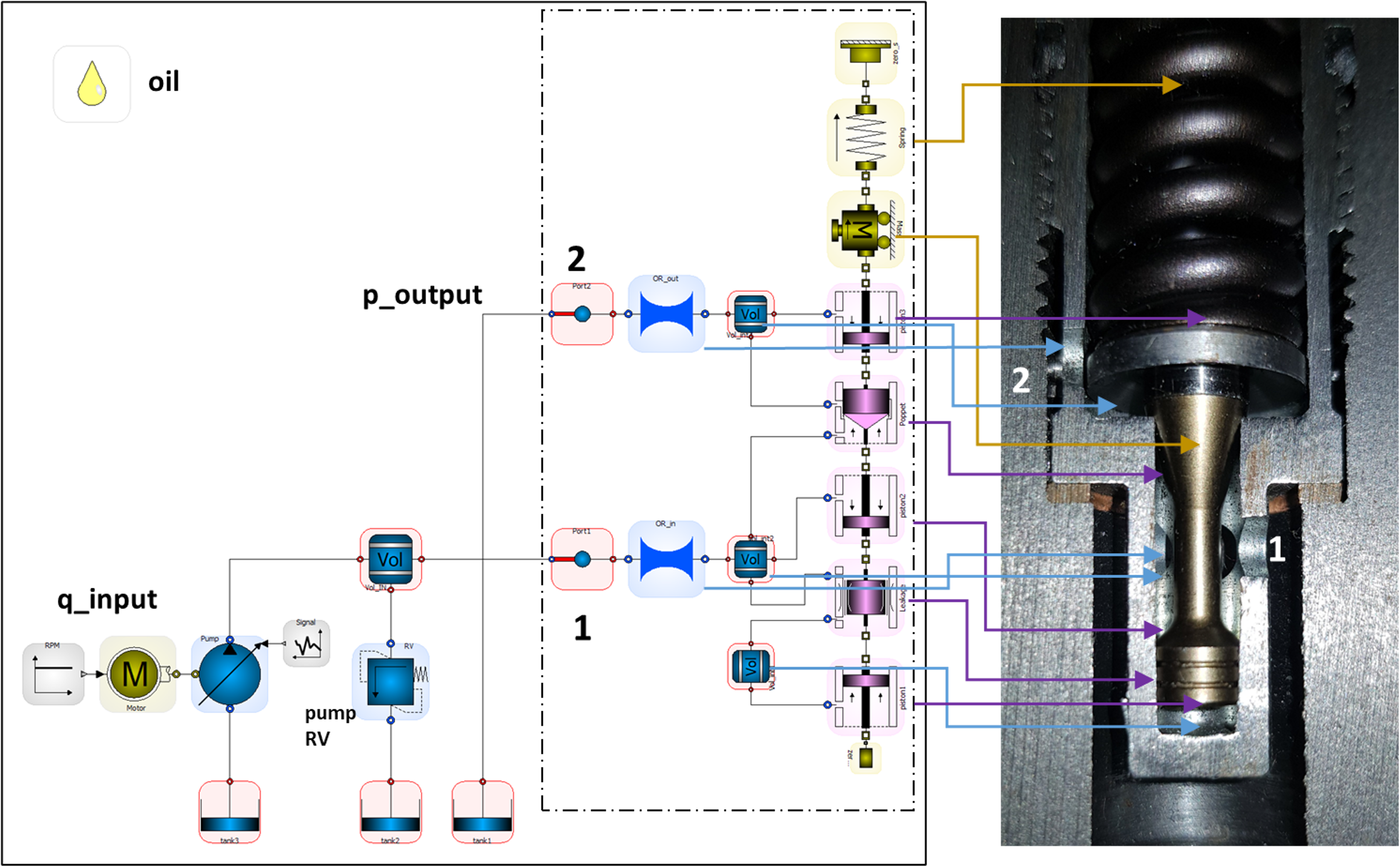
The hydraulic component is created in OpenModelica with the SmartFluidPower dynamic virtual library, using the libraries:
- ‘Hydraulic’ to model oil volumes and holes (with equivalent orifices), in addition to the elements to close the test circuit (flow source, upstream pressure relief valve and tank)
- ‘Components’ to model the moving part of the valve, ie poppet, stabilizer piston and leakage element
- ‘Mechanical’ to model the mass, spring and mechanical end stops
The image shows the real valve mounted in a sectioned manifold and its virtual prototype tested under the conditions explained above.
The simulations can be launched from the OpenModelica software but also from a customized user interface that makes it easier to use. An example of interface for this model is shown here.
Below are the results obtained with the virtual model of pressure drop and displacement of the mobile poppet in the two conditions tested. In particular, the variables are plotted as a function of the flow rate ramp in the first condition and of time in the second one.
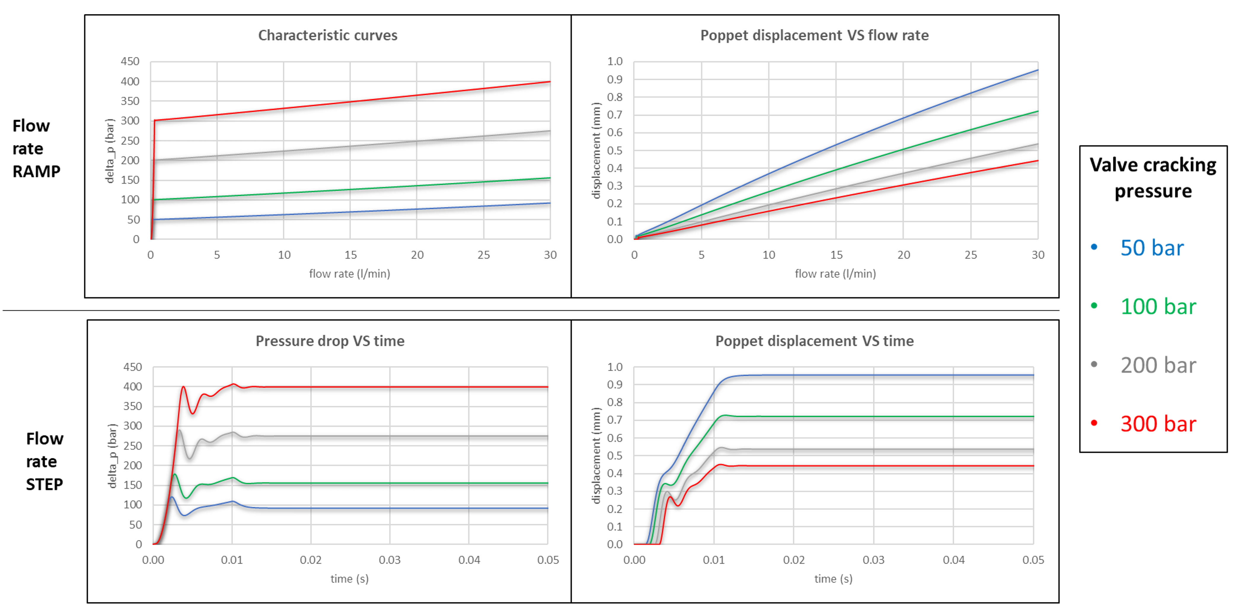
The results show that the maximum displacement of the valve poppet (obtained at 30 l/min and with the lowest simulated calibration) is about 1 mm. It is also possible to notice the operation of the stability system which limits the oscillations with an input flow pulse, both in the pressure and stroke values, and for the damping in a time of less than 20 ms.
In the model, all the geometric parameters of the component are set and an average contribution of the flow forces is assumed, even if the presence of the plate on the poppet could largely compensate them: for a more accurate calibration of the flow forces, CFD simulations on the geometry of the mobile component are done and the results are compared here.
Finally, the calibrated model of the hydraulic valve alone can be closed in a ‘box’, leaving only the parameters required by the user open for modification, and inserted in other hydraulic circuits (as shown here). In this way you can create a customized virtual library with your products to use them quickly in different test circuits or applications.