The pressure relief valve modeled here can be enclosed in a component that communicates externally with inlet and outlet ports (a).
The hydraulic component model is inserted in a customized library with its characteristic name and icon, and you can decide which parameters are open for quick modification: in example (b) calibration pressure and size.
Finally, the customized component can be simply inserted in other hydraulic circuits which, therefore, will be simulated using the real characteristics of the valve: in (c) a circuit with a double pump is shown that feeds a linear actuator with a resistant load.
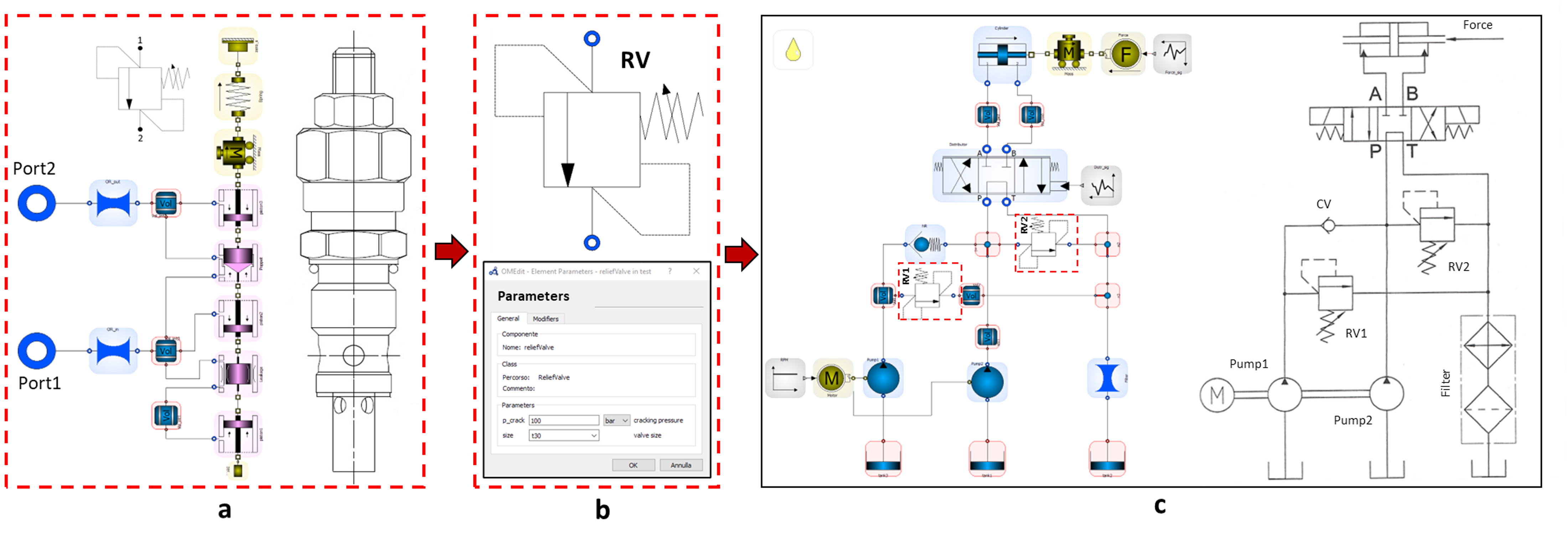
Below are the details of the hydraulic circuit components and operating conditions:
- Pump1 delivers 120 l/min, Pump2 delivers 30 l/min, both with fixed displacement
- Pressure relief valves (of the type modeled previously) RV1 is set at 25bar, RV2 at 100bar
- The flow is directed with Distributor, 4/3 open center electrically operated directional valve, with delta_p of 2 bar @ 150 l/min: up to 3s in central position, switched P-> A and B-> T from 3s (in 0.3 s) until the end of the cycle
- Check valve CV considered ideal
- Cylinder double-acting cylinder (double-rod), with diameters of 90 mm and 30 mm and stroke of 2.5m
- Filter block filter and chiller with delta_p of 1 bar @ 150 l/min
- Force resistant force of the load: 6 kN up to 8s, increases to 24kN from 8s (in 0.1s) to the end of the cycle
- 13s operating cycle
Running the simulation, the results shown below are obtained in terms of pressure in port A, flow rates in the cylinder and relief valves, and cylinder stroke, all as a function of the operating cycle time.
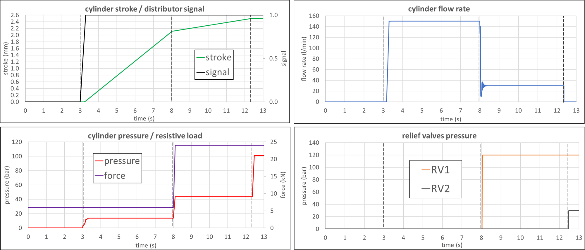
The results show the different phases of the cycle highlighted by the cylinder that makes a first faster stroke (from 3s to 8s), a second slower one and, in the last one, reaches the end of the stroke. The phases are also marked by the different flow rates, modified by the opening of the relief valves, and by the pressure in the cylinder imposed by the load. There are also some fluctuations in flow rate at time 8s, which corresponds to the opening of the larger size relief valve RV1.