Come trasformare in energia meccanica ciò che la valvola limitatrice normalmente disperde
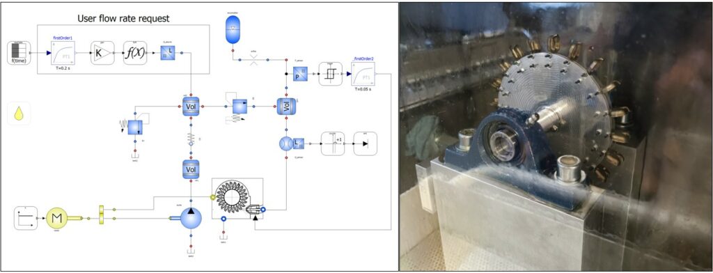
On the left the dynamic model of the hydraulic system created with the SmartFluidPower library. On the right one of the turbine prototypes built by ELT FLUID.
The most common pump-motor group in industrial hydraulics is still the simplest: a fixed-displacement pump, an electric motor, a pressure relief valve. It works fine as long as the load is constant — but almost no real duty cycle is. The actuator asks for flow intermittently, and for the rest of the time the power the pump generates is dumped by the valve as heat.
Replacing the pump with a variable-displacement one would fix the problem at the root, but isn’t always practical: higher cost, sensitivity to fluid contamination, slower response. In a research project carried out with the Fluid Power Lab of University of Modena and Reggio Emilia and Elt Fluid, presented at the GFPS 2022 PhD Symposium, we explored an alternative: recovering that energy without touching the existing pump, closing the system into a loop with a miniature Pelton turbine instead of a hydraulic motor — which, running intermittently and often without enough flow to lubricate its own clearances, would tend to overheat and wear out.
A machine outside its natural habitat. Pelton turbines are built for mountain hydroelectric plants: high heads, modest flow rates. Our circuit is almost the opposite — very high pressure, a tiny jet. The characteristic specific speed calculated for the system came out at around 0.01, at the very edge of the Pelton’s typical range (0.05–0.4), ruling out the direct shaft coupling originally planned: a reduction drive is needed. To size the turbine, two design methods were tested in parallel, producing two geometries with different trade-offs between friction, windage and rotational speed — the second let us move away from the ideal peripheral speed coefficient (0.5) to a more realistic 0.42, containing rotational speed and capping the bucket count at 20 for manufacturing reasons.
An accumulator to smooth the jet. The flow discharged by the relief valve arrives in bursts, following the gaps in the duty cycle. An accumulator placed upstream of the on/off valve acting as the nozzle solves this: it fills as pressure rises, discharges toward the turbine at the set maximum, and closes again at the minimum — turning a chaotic flow into regular injections.
What the simulation shows. The complete system was modelled with a lumped-parameter approach in OpenModelica, using SmartFluidPower’s dynamic library. Over a 40-second cycle, of the total wasted by the relief valve, 23% is lost anyway along the transmission line, leaving 24% of recoverable potential; the estimated net recovery is around 11%, depending on the specific duty cycle. Overall system efficiency rises from 53% without the turbine to 64% with it installed.
Two open issues remain: erosion of the bucket’s cutting edge from the jet, where even a few tenths of a millimetre of wear can noticeably affect efficiency, and air mixing into the oil as it passes through the turbine, which calls for adequate settling time in the tank. The two turbines designed have been prototyped and will be tested by Elt Fluid on the reference test rig — comparing experimental data against the model’s estimates is the next step.
The full paper, “System for recovering energy in hydraulic circuit by using a small Pelton turbine” (M. Rizzoli, G. Cillo, B. Zardin, D. Manfredi, M. Borghi — GFPS2022 PhD Symposium), is freely available at this link.