Quick start to OpenModelica
Once the OpenModelica software is installed through the 
OpenModelica Connection Editor application, you can launch the OMEdit.exe executable.
This guide takes the contents and offers a summary from the original documentation provided by OpenModelica, consult it for further details.
OMEdit – OpenModelica Connection Editor
OMEdit – OpenModelica Connection Editor is the new graphical user interface (GUI) for graphical modeling in OpenModelica. It is implemented in C++ using the Qt graphics library and supports the Modelica Standard Library included in the latest versions of OpenModelica.
OMEdit provides various user-friendly features for creating, navigating, editing, and simulating models:
- Modeling – Simple and intuitive creation of Modelica models.
- Pre-defined models – Navigation of the Modelica Standard Library to access provided models.
- User defined models – Users can create their own models for immediate use and for subsequent reuse.
- Component interfaces – Smart editing of connections to draw and modify links between component interfaces.
- Simulation – Subsystem for running simulations and defining simulation parameters, such as start and end time.
- Plotting – Interface for graphical visualization of variables resulting from simulations.
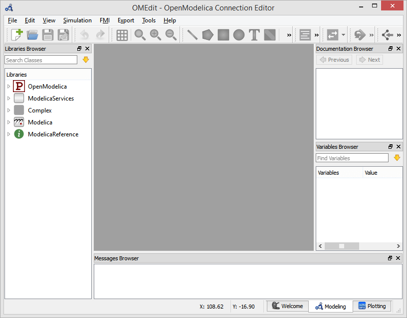
Main screen and related windows
The main screen (MainWindow) contains several dockable windows (browsers):
- Libraries
- Documentation
- Variables
- Messages
Libraries
This panel shows the list of loaded Modelica classes(1). All open files or packages will be displayed here. Each item in the Libraries Browser has a context menu (right-click) that allows quick management and use of the class.
- To view the Libraries Browser, select
View > Windows > Libraries.
Classes are displayed in a tree structure, with name and associated icon. Protected classes are not shown by default. To view them, you need to enable the Show Protected Classes option(1).
Tools > Options > Show Hidden Classes if not encrypted
Documentation
The Documentation Browser displays the HTML documentation of Modelica classes(1). It includes navigation buttons to move forward and backward and a WYSIWYG editor that allows writing documentation for personal classes in HTML format.
- To view
Documentation, selectView > Windows > Documentation.
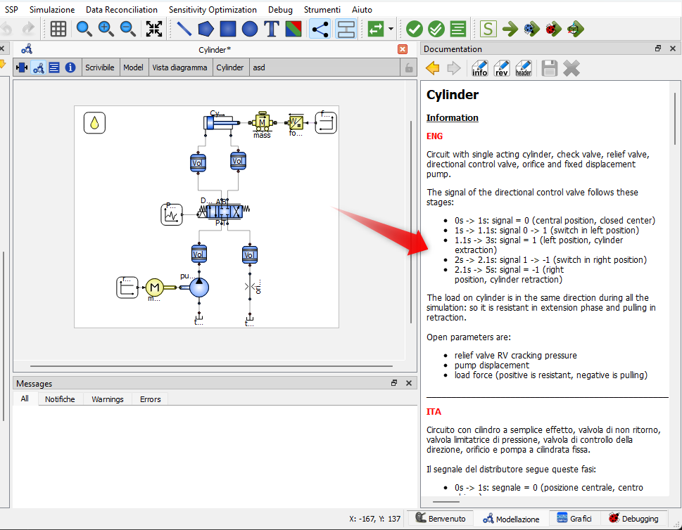
It allows inserting explanatory texts, images, or formulas regarding the use of the model.
It is useful for providing usage instructions, technical explanations, or design notes.
Consult the SFPLibDyn library documentation
Each model in the library comes with documentation to explain the model's purpose, operation, variables, and equations. Consult it to understand how each component of the library works!
Messages
The Messages Browser shows the list of errors. The following types of errors can occur:
- Syntax
- Grammar
- Translation
- Symbolic
- Simulation
- Scripting
For more details on Messages options, consult the Messages Options section of OpenModelica.
Perspectives
The software is divided into 4 main sections. You can navigate through the sections with the buttons located at the bottom right of the main window:

- Welcome
- Modeling
- Plotting
- Debugging
Welcome Perspective
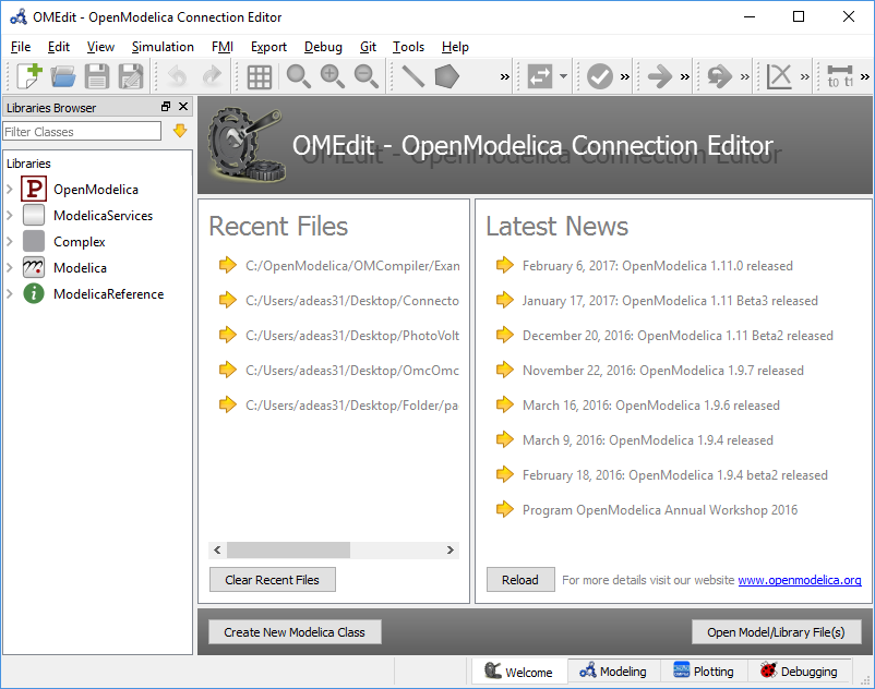
The Welcome Perspective shows the list of recent files and the latest news from OpenModelica.
The orientation of the recent files list and latest news can be horizontal or vertical. The user can also choose to show or hide the latest news (see the General Options section).
Modeling Perspective
The Modeling Perspective provides the interface through which the user can create and design their own models.
When a model is open, you can navigate through different views. To change view, you can use the buttons 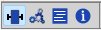 located at the top left in the main window. The selectable views are, in order:
- ICON VIEW
- DIAGRAM VIEW
- TEXT VIEW
- DOCUMENTATION VIEW
Icon View
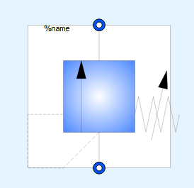
In this view, you can build the file's icon. This step is not very important if you are building a model to run a simulation, but it becomes important in the case of a Supercomponent to insert in another simulation file.
Here you can draw custom symbols using the software's graphic tools (rectangles, lines, texts, images, etc...)  present in the upper toolbar.
The generated icon is displayed in the library list on the left and in the diagram of any other file that calls the model.
Diagram View
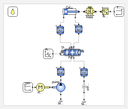
This is the most important view for basic use of the software and the library. In this view, you can visually build and connect models. It is used like a worksheet where, through graphical interaction, you can drag components from the library and connect them with graphical connections.
Each connection represents a physical or logical link (e.g., hydraulic lines, electrical signals, etc...).
It is the main view for creating complex diagrams and circuits.
Text View
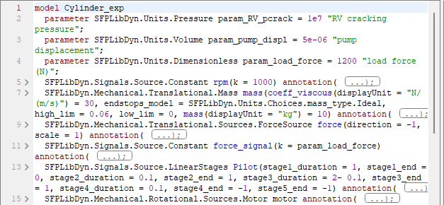
This view shows the Modelica code of the model.
Here you can write or manually modify the equations and declarations.
All graphical changes (Icon or Diagram) seen previously are automatically reflected in the code as well.
It is the reference view for users who want to check the model's implementation in detail.
Documentation View
The Documentation View button allows opening the Documentation Browser already described.
Plotting Perspective
The Plotting Perspective displays the results of model simulations. This perspective automatically becomes active when the simulation of a model ends successfully.
It is also activated when the user opens one of the result files supported by OpenModelica.
Similar to the Modeling Perspective, this perspective can also be displayed in tabbed view or sub-window view.
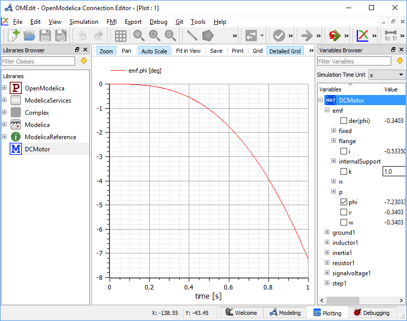
Variables
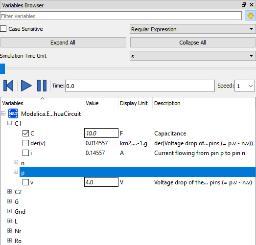
The class variables are organized in a tree structure and displayed in the Variables Window. Each variable is associated with a checkbox: by selecting it, the variable's values are plotted in the graph. The entire Variables Window can be collapsed or expanded using the Collapse All and Expand All buttons.
There is a search field to filter variables in the tree structure. By clicking the yellow downward arrow, you can set all filtering options. Filtering can be done via regular expressions (Regular Expression), wildcards, or fixed strings (Fixed String); in all cases, all variables whose full name contains a string matching the set filter are displayed. For more information on other rules that can be applied in the filter, consult the official documentation.
Debugging Perspective
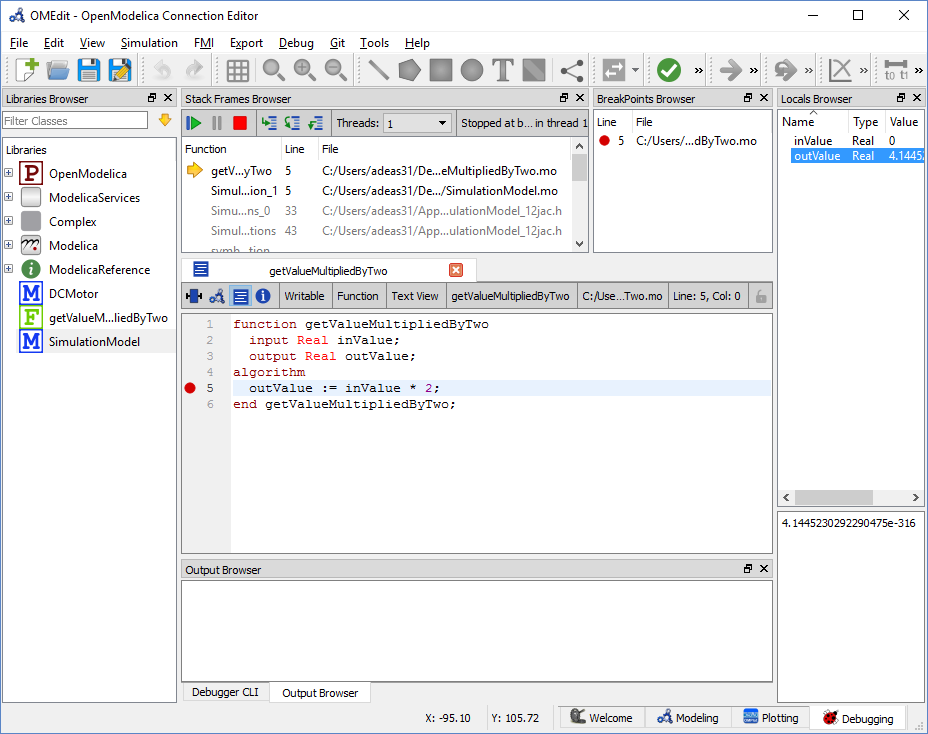
The application automatically switches to the Debugging Perspective when the user simulates a class using the algorithmic debugger.
This perspective shows the list of stack frames, breakpoints, and variables.
Simulation
Once the model is ready, you can set and launch the simulation through the buttons  . The first button opens the
 Simulation Setup tab which allows setting simulation parameters, while the second starts the simulation.
The simulation process in OMEdit is divided into three main phases:
Phase 1 – Model Translation
The Modelica model is translated into C/C++ code. Initially, the model is instantiated by the frontend, which transforms it into a "flat" set of variables, parameters, equations, algorithms, and functions. Then, the backend analyzes the mathematical structure of the flat model, applies symbolic simplifications, and determines how to solve the equations efficiently. Finally, based on this information, the model-specific C/C++ code is generated.
This part of the process can be influenced by setting the Translation Flags (also known as Command Line Options), for example to decide which types of structural simplifications should be performed during the translation phase.
Phase 2 – Compilation
The C/C++ code is compiled and linked to generate a simulation executable. Additional flags can be provided to the C/C++ compiler to influence this phase.
Since multiple C/C++ source files are generated for a single model, OMEdit compiles them in parallel, taking advantage of multi-core CPU capabilities.
Phase 3 – Simulation Execution
The simulation executable is launched and produces the simulation results in a .mat or .csv file. Runtime behavior can be influenced via Simulation Flags, for example by choosing specific solvers or modifying the output file name.
It is possible to re-run the simulation of a model multiple times, modifying parameter values from the Variables Browser and/or changing some Simulation Flags.
In this case, only Phase 3 is repeated, skipping Phases 1 and 2, allowing much faster iterations.
Simulation Options
The simulation options for each model are stored within OMEdit's data structure and are set according to the following sequence:
- Each model has its own translation and simulation options.
-
If the model is opened for the first time, the translation and simulation options are set to default values(1).
- They can be customized in
Tools > Options > Simulation
- They can be customized in
-
The
experiment,__OpenModelica_commandLineOptions, and__OpenModelica_simulationFlagsannotations are applied, if present in the model. - All changes made through the
Simulation Setupwindow for a specific model are maintained for the entire session. To reuse the same settings in future sessions, you must save them within theexperiment,__OpenModelica_commandLineOptions, and__OpenModelica_simulationFlagsannotations.
Launching the Simulation Setup
The Simulation Setup of OMEdit can be opened in the following ways:
- Selecting
Simulation > Simulation Setupfrom the menu (requires an active model). - Clicking the
Simulation Setupbutton in the toolbar (requires an active model in the Model Widget). - Right-clicking on a model in the
Libraries Browserand selectingSimulation Setup.
General Settings
Simulation Interval
Start Time– simulation start time.Stop Time– simulation end time.Number of intervals– number of simulation intervals.Interval– length of a single interval (i.e., integration step).
Integration
Method– simulation solver. See the Integration Methods section for details on solvers.Tolerance– simulation tolerance.Jacobian– method for calculating the Jacobian.